
Looking for an open-source CAD tool for your tablet? Look no further—Oscad is the answer!
Are you fascinated by electronic systems? Have you ever wondered how they work? Do you design electronic circuits as a hobby? Have you been discouraged by the high cost of proprietary design tools? Oscad is the answer! Oscad is a free and open-source computer-aided design (CAD) tool that lets you design, simulate, analyze and produce printed circuit board layouts for your favourite electronic circuits. Oscad is created using open-source software packages: KiCad (www.kicad-pcb.org/display/KICAD/KiCad+EDA+Software+Suite), Ngspice (ngspice.sourceforge.net), Scilab (www.scilab.org) and Python. It is useful for students, teachers, professionals and entrepreneurs who are looking for an alternative to expensive proprietary CAD tools.
This article introduces Oscad and its capabilities with a lot of illustrative examples. It also describes various resources, such as our book on Oscad Oscad: An Open Source EDA Tool for Circuit Design, Simulation, Analysis and PCB Design (www.oscad.in/resource/book/oscad.pdf), tutorials and example projects. Additionally, we outline initiatives to promote Oscad to the public.
Download the Oscad installer for Linux available at the Oscad Web page (www.oscad.in/downloads). Go to the Spoken Tutorial page (www.spoken-tutorial.org) and click on the Video Search option. In the Select Language drop-down menu, choose English and click Locate Tutorial. Listen to the Spoken Tutorial titled “Introduction to Oscad”. Follow the steps shown in the tutorial to install Oscad and validate the installation. Note that the tutorial covers the installation and use of Oscad in Ubuntu Linux.
To invoke Oscad, double-click on the Oscad icon on your desktop. Alternately, you can type oscad in a terminal to launch it. This opens up the Oscad project window (Figure 1).
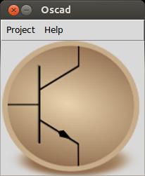
Figure 1. Oscad Project Window
Here you can open an existing Oscad project or create a new one. Click on Project and then New. Choose a directory and enter a project name. A vertical toolbar will open up. This is the Oscad Toolbar (Figure 2), and it has the following tools:
Schematic Editor: lets you create circuit schematics, perform electric rules checks and generate netlists for simulation and PCB design. EEschema (the schematic editor in KiCad) is used as the schematic editor.
Analysis Inserter: lets you add simulation parameters for DC, Nested DC, AC and Transient analyses.
Netlist Converter: converts the netlist generated by the schematic editor (EEschema) into Ngspice-compatible format. It also adds the analysis parameters generated by the Analysis Inserter, plot commands, model and subcircuit information and other control statements to the netlist.
Ngspice: simulates the netlist produced by the Netlist Converter and displays the results.
Footprint Editor: maps each component in the netlist to a corresponding footprint module. Manual and automatic mapping is possible. CvPcb (the footprint editor in KiCad) is used as the footprint editor.
Layout Editor: lets you create and edit PCB layouts for the circuit. PCBnew (the layout editor in KiCad) is used. It also lets you choose design rules, add layers, vias and plot Gerber files.
SMCSim: stands for Scilab-based Mini Circuit Simulator. It generates symbolic equations for the circuit and solves them using Scilab. This is a unique feature of Oscad. At the time of this writing, this feature is available only for analog circuits.
Model Builder: helps you build models for devices, such as diodes and transistors (BJT, MOSFET) in your circuit.
Subcircuit Builder: lets you create subcircuits and use them for simulation. For example, an operational amplifier like UA741 or a timer chip like LM555N can be defined as subcircuits. You can create your own subcircuits and attach them to the main schematic.
Together, these tools make Oscad a complete electronic system design suite.
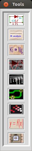
Figure 2. Oscad Toolbar
Let's look at the steps involved in the design of an electronic system. For simplicity's sake, let's consider the example of an RC circuit. The design flow is broadly divided into three stages.
Schematic Creation
Chapter 5 of our Oscad book explains schematic creation in detail. It also is covered in the Spoken Tutorial: Schematic Creation and Simulation Using Oscad (oscad.in/resources/tutorials/Oscad). First, let's create the schematic of an RC circuit. Click on the Schematic Editor tool from the Oscad toolbar to launch it. Add the Oscad libraries to your project using the Library option available in the Preferences menu. These libraries are available in the library folder in the Oscad installation directory. Add components to your schematic using the Place a Component option available from the right toolbar. Place a resistor, a capacitor, a ground and a sine source. Figure 3 shows the components placed in the Schematic Editor.
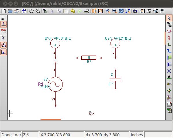
Figure 3. Components Placed in the Schematic Editor
Assign values to the components and connect them using wires as shown in Figures 3 and 4. Annotate the schematic and check for electric rules (erc). You may want to connect voltage or current plot components for viewing outputs after simulation, but these are not required for PCB design. Figure 4 shows the completed circuit schematic for simulation. Note the additional component PWR_FLAG. This is used to eliminate erc errors.
Netlists can be generated separately for simulation and PCB design. Click on Generate Netlist from the top toolbar and choose Spice. Uncheck the option Prefix references “U” and “IC” with “X” and click on Netlist. Save the netlist. It has extension .cir.
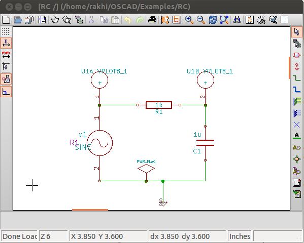
Figure 4. Final RC Circuit for Simulation
Simulation
Chapter 6 of our Oscad book details simulation of circuits using Oscad. This is also explained in the Spoken Tutorial: Schematic Creation and Simulation using Oscad. The steps are as follows. Click on the Analysis Inserter tool from the Oscad toolbar to add simulation parameters. Choose Transient, and enter the parameters: start time = 0 seconds, step time = 5 ms (milliseconds) and stop time = 30 ms. Click on Add Simulation Data (Figure 5). Save and exit, and don't change the filename. Next, click on the Netlist Converter tool from the Oscad toolbar. Enter the parameters of the sine source: offset = 0, amplitude = 5, frequency = 50, delay time = 0 and damping factor = 0 (Figure 6). Press Enter to quit. Click on the Ngspice tool from the Oscad toolbar to simulate the circuit and view the output plots. Figure 7 shows the plots.
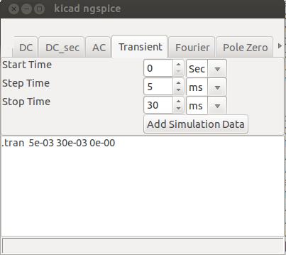
Figure 5. Adding Simulation Parameters
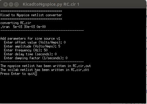
Figure 6. Give parameters for the sine source during the netlist conversion.
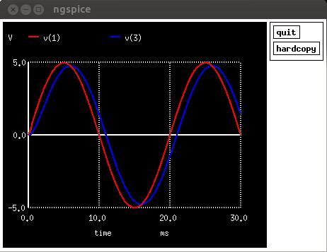
Figure 7. Transient Simulation Output of the RC Circuit
PCB Design
Once you are satisfied with the simulation results, you can start the PCB design. You may want to replace the sine source with a connector in your schematic. Remove the plot components. Figure 8 shows the modified schematic for the PCB design.
Next, let's generate the netlist for the PCB design. To do this, click on Generate Netlist, select Pcbnew, and click on Netlist. Note that the extension of the netlist is .net. Save the netlist, and save and close the Schematic Editor. Chapter 7 of our Oscad book explains PCB design using Oscad. You also can refer to the Spoken Tutorial: Designing Printed Circuit Board using Oscad. There are two stages in PCB design, and they are explained below.
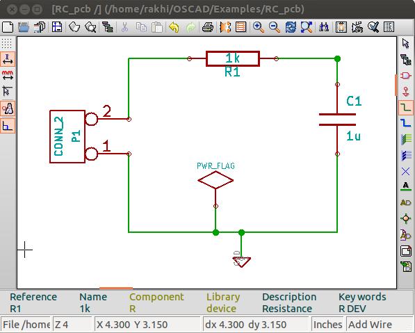
Figure 8. Final Schematic for PCB Design
1) Footprint Mapping
The first step in PCB design is to assign a footprint to each of the components in the schematic. Footprint refers to the physical layout (for example, through-hole, surface mount) on the printed circuit board to which the component will be mounted. Click on the Footprint Editor tool from the Oscad toolbar. It shows the components in your design on the left side and the available footprints on the right side. You can assign footprints to your components either manually or automatically. Figure 9 shows the final component list with the footprint mapping done. You can view the footprints in 2-D and 3-D. Browse and save the netlist in the project folder and close the Footprint Editor.
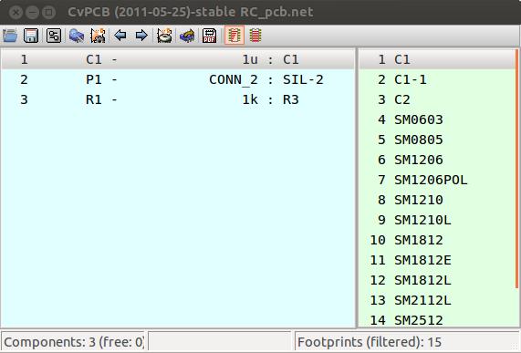
Figure 9. Footprint Mapping for the RC Circuit
2) Layout Design
Launch the Layout Editor from the Oscad toolbar. Import your netlist using the Read Netlist option in the menu bar. Then browse and open the netlist. Click on Read Current Netlist. The component footprints will be placed in the top-left corner of the layout editor window. Place them at the center of the editor window. Figure 10 shows the footprint modules of the RC circuit placed at the center of the layout editor window.
Arrange the components to minimize track length. Specify design rules like Track Width, Via Diameter and so on using the Design Rules menu. Choose the PCB layer from the layer options on the right and start drawing tracks. To draw a track, use x the shortcut key. Figure 11 shows the final placement of the components, and Figure 12 shows the tracks drawn. This is a single-layer PCB layout, with a track width of 0.8mm. Complete the layout by drawing PCB edges.
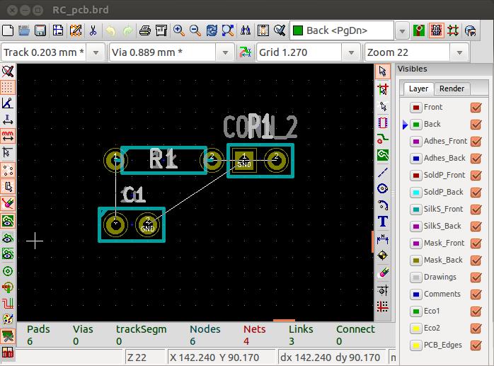
Figure 10. Footprint Modules of the RC Circuit at the Center of the Layout Editor Window
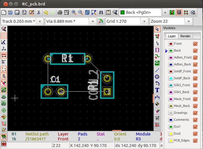
Figure 11. Final Placement of Footprints of the RC Circuit
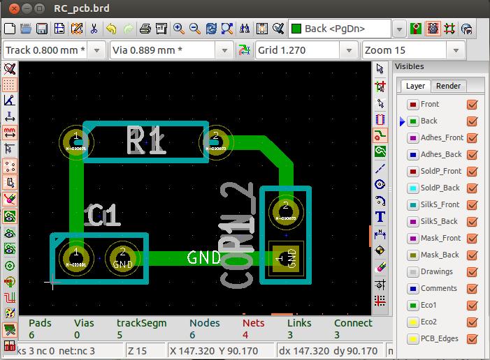
Figure 12. All Tracks Drawn, Single-Layer PCB Layout
You can create multi-layered PCB layouts using the Layout Editor. You can create your own footprint modules too. You also can get a 3-D view of the layout you created. Figure 13 shows the 3-D view of the PCB layout created above.
Do a design rules check by clicking on the Perform design rules check option from the menu bar. Ensure that there are no errors, and save your board. You can choose to generate Gerber files for your PCB. You also can get DXF/HPGL/PostScript plots of your PCB layout. Now you are ready to fabricate your PCB!

Figure 13. 3-D View of the RC Circuit PCB Layout
Oscad has the following advanced features:
Model Builder
Subcircuit Builder
Scilab-based simulator
Model Builder
The accuracy of the simulation depends on the accuracy of the models used. In Oscad, the user can define and edit device models. Currently, this feature incorporates models for diodes, BJTs, MOSFETs and so on. To illustrate the Model Builder's features, let's look at the example of a Bridge Rectifier circuit using diodes. Figure 14 shows the circuit.
Launch the Model Builder tool to edit the diode model. Figure 15 shows the GUI to key in the diode's parameters. You can enter the model parameters as given in a datasheet of your device. Save the model. You can re-use this model in other projects using the Export option (Chapter 8 of our Oscad book explains the Model Builder in more detail).
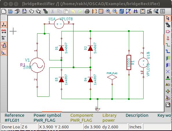
Figure 14. Bridge Rectifier Circuit Using Diodes
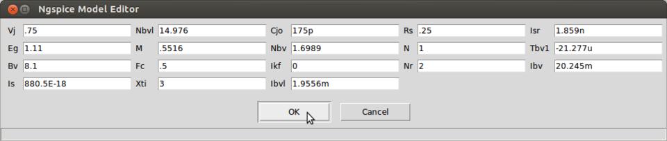
Figure 15. GUI to Edit the Diode Model
Subcircuit Builder
The Subcircuit Builder helps you break complex circuits into subcircuits. These subcircuits can be re-used in other projects. This approach makes designs scalable, hierarchical and modular. Let's look at the example of the Astable Multivibrator that uses a 555 timer (LM555N). Figure 16 shows the Astable Multivibrator circuit. To develop the LM555N subcircuit, launch the Subcircuit Builder tool and create the internal schematic for LM555N. Figure 17 shows the subcircuit of LM555N. Note the port connections.
The Oscad subcircuit library already has subcircuits for LM555N, UA741 and so on. (See Chapter 8 of our Oscad book for more details on the Subcircuit Builder.)
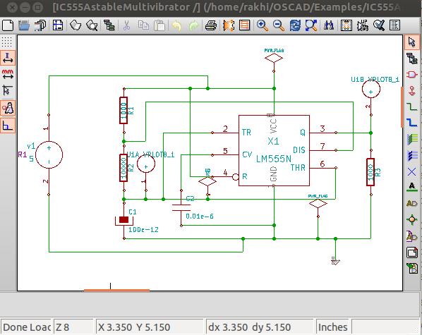
Figure 16. Astable Multivibrator Circuit Using a 555 Timer
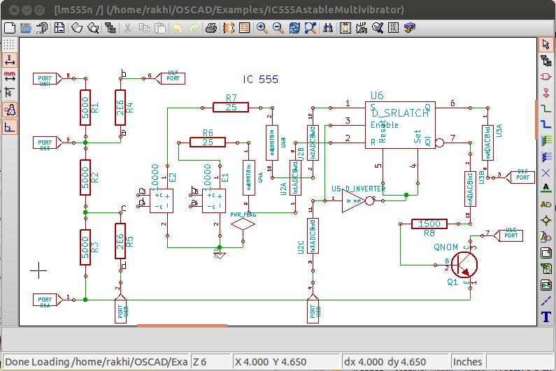
Figure 17. LM555N Subcircuit
Scilab-Based Mini Circuit Simulator (SMCSim)
Simulators use mathematical models to model the behavior of electronic circuits. Unfortunately, no simulator gives the system of equations it solves. This impedes understanding of how a circuit simulator works. SMCSim provides mathematical equations that replicate the behavior of the circuit. This feature is unique to Oscad. It gives users more insights into their circuits and helps them appreciate the simulation results.
SMCSim works in three modes: normal, symbolic and numerical. In normal mode, SMCSim solves the circuit equations and gives the final simulation result. In symbolic mode, it gives symbolic equations along with the result. In numerical mode, it gives symbolic equations, intermediate numerical values of the components and elements in system matrices, and the final simulation result. Figure 18 shows the equations generated for the Bridge Rectifier circuit presented earlier. It also shows the SMCSim simulation results. (Chapter 9 of our Oscad book explains more about SMCSim.)
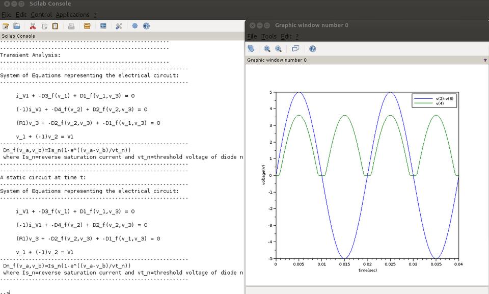
Figure 18. Equations for Bridge Rectifier Circuit and SMCSim Simulation Results
Aakash (aakashlabs.org) provides a great platform for learning and education. It can run GNU/Linux and most GNU/Linux applications (aakashlabs.org/builds/linux-on-aakash_CSI_July03.pdf). As KiCad, Ngspice, Scilab and Python run on GNU/Linux, you easily could port Oscad also onto the Aakash. As the Aakash tablet costs about $35, for less than $40 (including a keyboard and a mouse), you can have access to a powerful CAD system. This can help students who are enthusiastic about circuit design but can't afford expensive hardware and software.
Installing Oscad on Aakash is similar to its GNU/Linux desktop version. You can follow the same instructions for the desktop version mentioned earlier in this article. The benefit of using Oscad on Aakash lies in its portability and performance. Although a capacitive touchscreen is available on Aakash, you can attach an external keyboard and mouse. Sometimes keyboard shortcuts are easier to use than touch controls when running design and simulation tools. Figures 19 and 20 show a few photographs of Oscad running on Aakash.
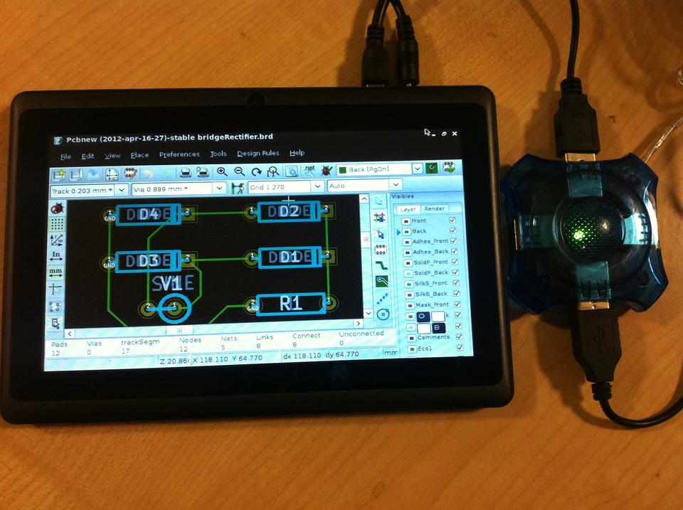
Figure 19. PCB layout of Bridge Rectifier on Aakash. A USB hub is used with Aakash to connect a mouse and a keyboard.
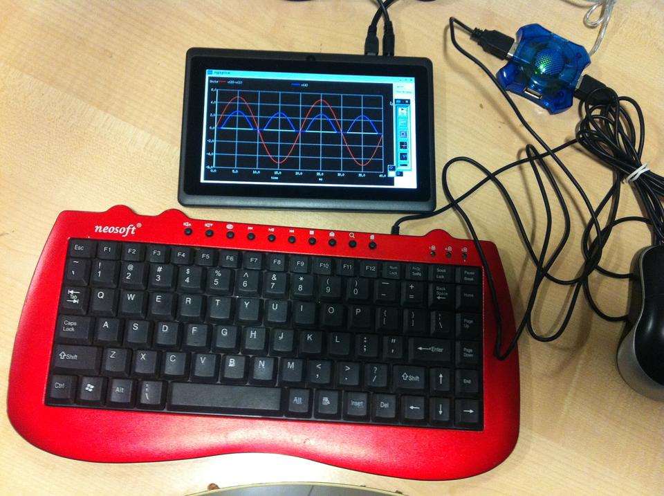
Figure 20. Oscad running on Aakash with an external keyboard and mouse attached. It also shows output from Ngspice.
Three Spoken Tutorials that explain installing and using Oscad are available. As Oscad uses KiCad and Ngspice, two different sets of tutorials on each of these also are available. You can download all the tutorials from www.spoken-tutorial.org. We recently published a book on Oscad titled Oscad: An Open Source EDA Tool for Circuit Design, Simulation, Analysis and PCB Design published by Shroff Publishers and Distributors, June 2013 (www.shroffpublishers.com/detail.aspx?cat=0&title=5687). An e-version of this book is available free of charge at www.oscad.in/resource/book/oscad.pdf for non-commercial use. Lots of example projects are also available at www.oscad.in/downloads to help you get started.
We have a host of activities through which we promote the use of Oscad:
SELF workshops through Spoken Tutorials: these are two-hour workshops conducted using Spoken Tutorials and an associated instruction sheet. An institution that wants to organize a SELF workshop should provide the following: 1) A volunteer (who can be a faculty member or a student), 2) one computer per participant with audio output capability, and 3) one head-phone per participant. We get very encouraging feedback from SELF workshops conducted all over India.
Textbook Companion on Oscad: an Oscad Textbook Companion (OTC) provides Oscad-based circuit schematics, simulation results and PCB design for solved problems from standard textbooks on electronic circuits. OTCs are available for Microelectronic Circuits: Theory and Applications 5th edition, Adel S. Sedra, Kenneth C. Smith, Oxford University Press (2009); and Electronic Devices and Circuit Theory 10th edition, Louis Nashelsky, Robert L. Boylestad, Pearson (2009). You can download them free of charge from www.oscad.in/textbook_run. OTCs for three more textbooks are currently in progress (www.oscad.in/books_progress). We invite students, teachers and professionals to create OTCs for other standard textbooks as well. OTC not only creates a large pool of useful projects in Oscad, but it also helps us identify any shortcomings in Oscad.
Lab Migration: this service helps laboratories that use proprietary tools shift to Oscad. Interested institutes should contact us expressing their intent and a statement of their lab experiments. Our team will provide the equivalent Oscad code to help conduct the experiments. The required coding will be done by our team and/or student/teacher volunteers from other institutes. This code will be available free of charge from www.oscad.in to everyone.
Oscad is a very powerful open-source CAD tool, and it is continually evolving. We are constantly adding more features to Oscad. We have now integrated breadboard simulation using Fritzing (fritzing.org/home) and circuit modeling and optimization using OpenModelica (https://openmodelica.org). We will be releasing these in the next version of Oscad. We are in the process of greatly expanding the mixed signal design/simulation capability in Oscad by integrating GHDL (ghdl.free.fr) with Ngspice. We welcome you to try out and use Oscad, and we would love to hear your feedback. We invite Linux enthusiasts from all over the world to partner with us and help enrich Oscad.
Oscad has been developed by the FOSSEE team (fossee.in), with funding from the National Mission on Education through ICT, MHRD, Government of India.
