
Got lots of 8mm film but no projector? Would you like to see those 30-year-old home movies your parents made when you were a kid one more time? Here's how a Linux system can be used to convert 8mm film to DVD movies.
Media Conversions, my business, converts videotape and slides to DVD. My customers often ask if I also can convert 8mm film. This is the story of my adventure into converting film to DVD. There are a number of ways to make a conversion. You can run the film through a projector and use a video camera to capture the images. Although, finding a working projector is difficult. Belts and rubber drive components dry up. Worse, 30-year-old rolls of film, some with splices, may no longer stand up to the stress of being projected at 18 frames/second (f/s). Plus, most video cameras run at 30f/s and will not synchronize with the projector.
Telecines have been used since the early days of broadcast TV to convert film to video. A number of Web sites describe DIY Telecine projects (see Resources). Generally, they either rebuild a projector and use a still camera, or they utilize a flatbed scanner and a custom film transport. Based on my research, I decided to build a Telecine using a flatbed scanner. The cost of entry is low, and scanners running at 3,000dpi or above are a commodity item. You can get started on the conversion software without the film transport, and you don't need custom optics. The downside, if you're not a programmer, is that you have to write all of your own software.
I decided early in the project that I wanted to use only open-source software tools. I hosted it on an Ubuntu Linux desktop system. I knew I would need a programming language with support for scanning, serial (or parallel) port communication, a math library and an image library. A plotting and drawing library also would be helpful during program development. I also wanted a language that offered ease of programming in higher-level constructs. I was familiar with C, but did not want to use it for this project, so instead, I decided to use Python. Python is easy to learn, it's well supported by the Linux community in both on-line forums and with numerous examples of code, and error handling and type checking/conversion are part of the language. Plus, the Python Imaging Library includes an interface to SANE for scanner support.
I acquired an Epson Perfection 3490 photo scanner for the project. It has SANE drivers, a built-in backlight for film scanning and offers 3,200dpi resolution.
There are four steps to converting a roll of film: scan the film in segments, find the image frames in the segments, remove duplicate frames where the segments overlap and make a movie from the frames. I wrote three separate Python programs for the first three steps and used FFmpeg for the fourth. The software relies on cheap disk space. Frame files are copied from segment scans. Overlap removal makes a second, renumbered, copy of all of the frame files. This strategy allows each of those programs to be rerun with the same segment scans for debugging and program development.
The cost, for a 50-foot roll of film, is approximately 8GB of space for the segment scans and similar amounts of space for the log file (if debug is turned on) and each of the frame file sets. Files are written into subdirectories of the current directory and numbered sequentially. A root filename, given as a command-line argument, is used as a prefix. Scan data is written into the scans directory, and frame files are written to the frames directory. If logging is turned on, log files are written to the logs. If debug is left on (default setting), marked up copies of the scan files also are written to the logs. The markings show where the edges of the sprocket holes were found and the outline of the frame extracted. Finally, overlap-removed, renumbered frames are written to the movie directory.
The program for scanning film simply calls the SANE scanner interface, saves the scan data, advances the film and repeats for a count given as an argument on the command line. See the Film Transport sidebar for a description. You can do a project like this without a film transport, but it's tedious. Each scan takes about 80 seconds. Limits on the size of the backlight meant that I could use only about 7.7 inches out of the approximately 8.5 inches of scanner width. Allowing for overlap between the scans, a 50-foot roll of film will have about 90 scan segments and takes roughly two hours to scan.
Film Transport
There are two parts to this project. One involves the software that processes the scanned film and makes a movie. The other part is the design of a film transport. The film transport is the harder part of the project, because it involves creating one-of-a-kind hardware. My transport design is based on reel-to-reel tape recorders popular in the 1960s (Figure a). It feeds film from a supply reel, across the scanner and winds it up on a take-up reel. A pair of spring-loaded idlers maintains film tension. A sprocket drive advances the film.

Figure a. 8mm Film Transport—Photo by Frank Pirz
The film transport is controlled by an embedded microprocessor. It takes commands from the Linux system over a serial port, and controls supply and take-up reel rotation and a sprocket motor for advancing the film. I was able to find both a program development and device programming environment as well as a C compiler for the Microchip PIC series of microprocessors all running under Linux. See Resources for the list of software tools used in this project.
To simplify the software, I made a film guide out of 10mm thick clear plastic film. I first aligned a steel ruler with the scanner axis, and I used GIMP to examine scans of the ruler edge. I moved it between scans until it was aligned to within approximately 50 pixels with the grid in GIMP. At 3,200dpi, 50 pixels is about 0.015 inches and more than adequate for this application. Then, I placed a piece of plastic against the ruler and glued it down with CyanoAcrylate glue. Once the glue was dry, I removed the ruler and used a piece of 8mm leader as a spacer to glue down a second guide. A sheet of glass placed over the guides keeps the film being scanned in alignment. With the film aligned with the scanner, no corrections for skewed images are necessary.
The program for finding frames actually is looking for sprocket holes. It's substituting software registration for mechanical registration of the film. Figure 1 shows a short piece of scanned film. The left-hand side is the original scan, and the right-hand side is the same scan converted to black and white (B&W).
Before we look for sprocket holes, we first find the top edge of the film. Given the alignment of the film in the guides, we could skip this step, but at this point, I'd rather not. The location of the top edge and knowing whether it's Regular8 or Super8 film (see the A Short History of 8mm Film sidebar), tells us approximately where the centerline of the sprocket holes will be.
The next step is to find the first sprocket hole. Because we are searching in a B&W image, we use a simplified correlation method. The search is done on a vertical line that spans the centerline we just found. If we find a white line, we add its value in to the correlation for that point. Black lines add zero. We have to look only at points inside the correlation window. Outside the window, the correlation value is zero. The process is sometimes called xor correlation, because addition replaces multiplication. The peak of the correlation function marks the edge of the sprocket hole.
With the edges of the first sprocket hole located, we know approximately where the centerline of the next sprocket hole should be. Simple line searches left and right from that centerline are used to find the next set of sprocket hole edges. The search ends at the last sprocket hole in the segment. Once we have found the left and right edges, we search up and down to locate the top and bottom edges. The film in Figure 1 shows the sprocket hole and frame markup after scanning.
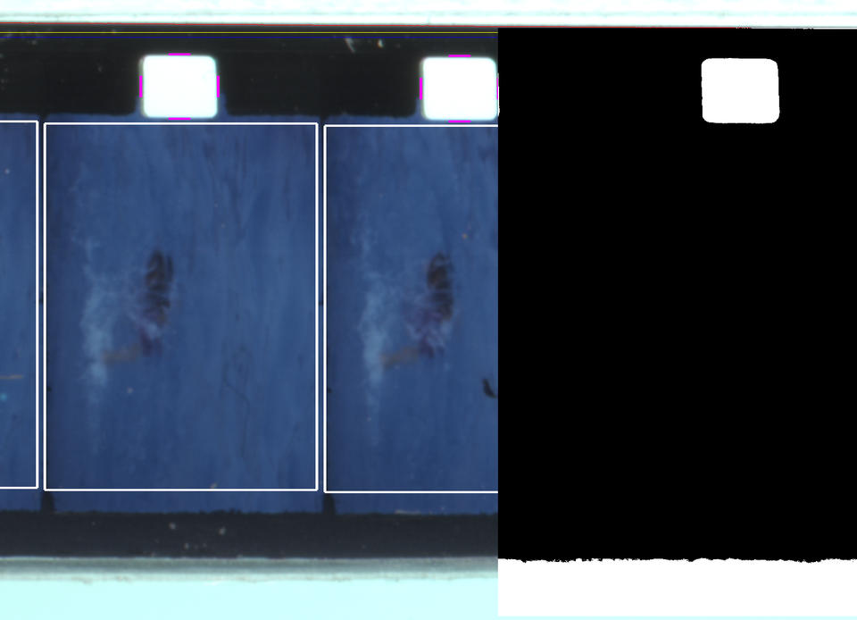
Figure 1. Sample 8mm Film—Used by Permission of Larry Stein
If everything were that simple, we would be done. Naturally, it's not. The film segment in Figure 2 illustrates two problems. First, Kodak edge-marks its film. It says “safety film”. Second, the image is not restricted to the frame area and has overlapped into the sprocket hole. Parts of the top and bottom edges of the sprocket hole have vanished in the B&W image. This will cause an edge-detection failure. There is a variety of heuristic methods to treat edge-detection failures. For left or right edge failures, I substitute the expected location based on the approximate sprocket center and the standard for the sprocket hole width. For top or bottom failures, my choice is to post-process the table of edges. When I find a missing edge or a run of missing edges, I average the edge values on either side of the gap and use the average as the location of the missing edge. It's important not to have abrupt changes in the sprocket hole locations, as this leads to visible jitter in the movie image.
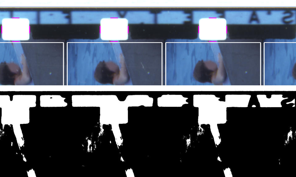
Figure 2. Illustrating Edge Failures—Used by Permission of Larry Stein
Once all of the sprocket holes are found, the image frames are written to separate files in the frames subdirectory. The sprocket hole edge locations are written out to the log file. Although I have not yet needed to do so, at some point, I expect to encounter a film segment where I cannot locate all the sprocket hole edges. Heuristic methods will take you only so far. It will be easier to use GIMP to find the elusive sprocket hole edges and edit the log file table with the correct coordinates. A modified version of the frame finding program could read in the corrected log file table and use that data to generate the image frames.
The images in the first movie I converted would get brighter and then get dimmer with a cycle of about 2–3 seconds. It was very visible and made the movie unusable. I'm scanning 45–46 image frames in each segment of film. At 18f/s, that's about 2.5 seconds of film. I'm using the film backlight removed from the cover of the scanner. It's a cold cathode fluorescent lamp with a white plastic diffuser in front of it. It was intended to backlight 35mm slides. It turns out that its light output is not uniform from end to end. Like most fluorescent lamps, it's slightly dimmer at the ends. Projector manufacturers go to significant lengths to make sure that the film is uniformly illuminated. See the link in Resources on Köhler Illuminators for more details. Replacing the lamp with a longer one didn't fix the problem.
An e-mail conversation with Richard J. Kinch led me to put illumination compensation into the software. I scanned a piece of neutral density film. Don't have any available? I didn't either. I cheated. I cut up a gray anti-static storage bag into strips. Two layers of the plastic film brought the resulting image into the middle of the gray scale. Then, I divided the scan into segments and sampled the image at the center of each segment. Not surprisingly, there was about a 30% variation from each end to the center. As the individual frame files are written out, a location-dependent compensation value is applied. This eliminated the illumination variation from the movie.
The final step is to remove the duplicate images where the scan segments overlap. The amount of overlap depends on how far you advance the film between scans. For this Telecine design, we have traded frame-accurate mechanical registration for software registration. We are not trying to be precise with the film advance. Typical scan segments overlap by two or more frames. The method for detecting a match between frames is called correlation. If two image files are identical, their correlation will be 1.0. If they differ, it will be less than 1.0. In practice, image frames of the same image scanned at either end of the scanner do not match precisely. The program for removing duplicates copies and renumbers frames to the end of the current segment. It matches the next-to-last frame of the current segment with the first five frames of the next segment. The frame with the highest correlation is the matching frame. The next segment becomes the current segment, and frame copying and renumbering begins with the frame after the best match. The process ends when there is no next segment.
At this point, we have converted the movie. It's just not in a format that is very usable. Some video editing software is capable of importing a sequence of image files and then writing out a movie file. Many do not. However, we are not really interested in editing the movie. We want to convert it and give it back to the customer. Using an editing program would be cumbersome. Instead, we use FFmpeg to read in the image frames and create a movie file in a format that's ready to burn on a DVD. A sample command line looks like this:
ffmpeg -r 18 -i movie/sam.%4d.tiff \
            -target ntsc-dvd -aspect 4:3 sam.mpg
Briefly:
-r 18 tells FFmpeg that the input file is at 18 frames/second.
-i movie/sam.%4d.tiff implies the input files are named sam.0001.tiff, sam.002.tiff and so on.
-target ntsc-dvd -aspect 4:3 uses FFmpeg presets to create an .mpg movie file suitable for burning to DVD.
sam.mpg is the generated movie file.
Consult the on-line documentation and the reference cited in the Resources section for more information. At this point, our job is done. A variety of Linux tools is available for authoring DVDs and burning DVD disks. Both are beyond the scope of this article.
This project demonstrates that customized, relatively sophisticated, image processing can be handled easily with Linux-based tools. It also describes embedded hardware development in a Linux environment. This project is continuing to evolve. Sprocket hole edges can be checked for abrupt changes. Once the frame files are extracted, there are opportunities for additional improvements. I have experimented with the ImageMagick toolset to sharpen the images and remove dust specks. The Python programs for image processing as well as the C code and other engineering documents for the film transport are both available from the LJ FTP site.
